This product has limited availability. It will be replaced by: CSAT3C. Some accessories, replacement parts, or services may still be available when it is no longer available.
Designed for flux and other turbulence research projects


Visão Geral
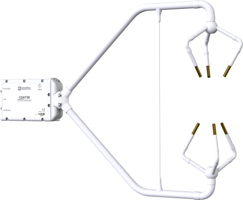
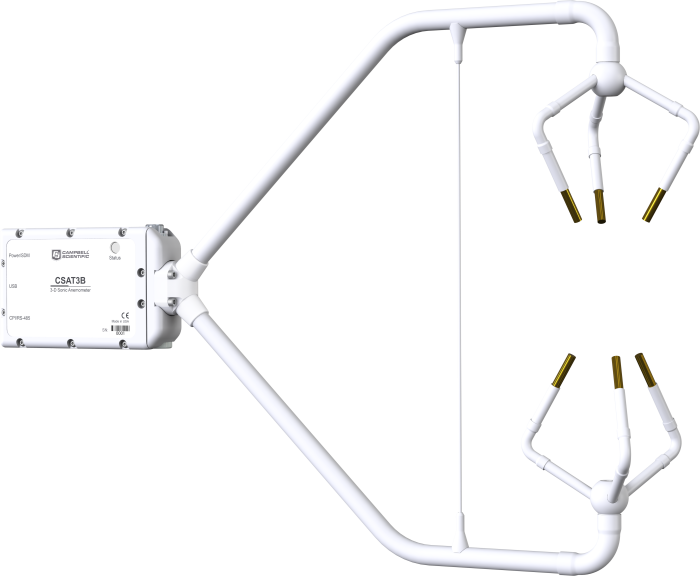
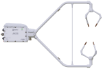
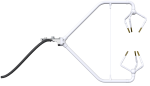
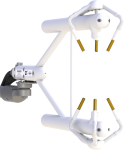
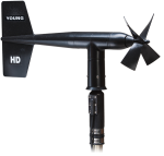
Campbell Scientific’s CSAT3B 3-D Sonic Anemometer is an update and replacement to the original CSAT3, and remains the 3-D sonic anemometer of choice for eddy-covariance measurements. It has an aerodynamic design, a 10 cm vertical measurement path, operates in a pulsed acoustic mode, and withstands exposure to harsh weather conditions. Three orthogonal wind components (ux, uy, uz) and the sonic temperature (Ts) are measured and output at a maximum rate of 100 Hz.
The most conspicuous innovation of the new design is the elimination of the electronics box. Instead, the electronics are packaged inside the mounting block of the CSAT3B head. This design feature makes installation easier and offers greater flexibility in instrument placement.
Measurements can be triggered from three sources:
- Data logger SDM command
- Data logger CPI command
- CSAT3B internal clock
The SDM and CPI protocols both support mechanisms for synchronizing multiple CSAT3Bs.
Benefícios e Características
- New conformal coating helps protect sonic transducers in corrosive environments
- Integrated electronics that provide easy mounting of a single piece of hardware
- Integrated inclinometer
- High-precision measurements ideal for turbulence and eddy-covariance studies
- An improved design with a thin, aerodynamic support strut close to the ends of the sensor arms, creating greater rigidity and improved accuracy of sonic temperature
- Data logger sampling supported for any frequency between 1 and 100 Hz
- New CPI communications for more robust, higher bandwidth measurements
- Multiple communication options including SDM, CPI, USB, and RS-485
- Internal temperature and humidity measurements with easily replaced desiccant
- Version 5 algorithm for calculating data outputs; combines the signal sensitivity of version 3 with the rain performance of version 4
- Includes options to filter high frequencies for applications requiring analysis of non-aliased spectra
imagens
3D / CAD Files:
Produtos Relacionados
Compatibilidade
Please note: The following shows notable compatibility information. It is not a comprehensive list of all compatible products.
Data Loggers
| Product | Compatible | Note |
|---|---|---|
| CR1000 (retired) | ||
| CR1000X (retired) | ||
| CR300 (retired) | ||
| CR3000 (retired) | ||
| CR310 | ||
| CR350 | ||
| CR6 | ||
| CR800 (retired) | ||
| CR850 (retired) |
Additional Compatibility Information
The CSAT3B works with standard USB ports on most computers. However, for consistent communications—especially when using multiple USB devices or lower-powered ports (such as those on laptops or hubs without power)—we recommend using a powered USB hub for optimal performance.
Especificações
| Sensor | 3-dimensional sonic anemometer |
| Measurement Description | Highest-quality wind speed and direction |
| Operating Temperature Range | -40 to +50°C (equivalent to 305 to 368 m s-1 in speed of sound) |
| Outputs | ux, uy, uz, Ts (ux, uy, uz are wind components referenced to the anemometer axes; Ts is sonic temperature in degrees Celsius.) |
| Signal Type/Output | SDM, CPI, USB, RS-485 |
| Speed of Sound | Determined from three acoustic paths. (Corrected for crosswind effects.) |
| Wind Direction Range | 2.5 to 357.5° in CSAT3B coordinate system (0 to 360° customized) |
| Range | ± 65 m s–1 (full-scale wind) |
| Filter Bandwidths | 5, 10, or 25 Hz |
| Measurement Path Length | 10.0 cm (3.9 in.) vertical; 5.8 cm (2.3 in.) horizontal |
| Transducer Angle from Horizontal | 60 degrees |
| Ingress Protection | IP67 |
| Transducer Diameter | 0.64 cm (0.25 in.) |
| Transducer Mounting Arm Diameter | 0.84 cm (0.33 in.) |
| Support Arm Diameter | 1.59 cm (0.63 in.) |
| Anemometer Head Weight | 1.45 kg (3.2 lb) |
| Anemometer Dimensions | 60.64 x 12.2 x 43.0 cm (23.87 x 4.8 x 16.9 in.) |
Wind Accuracy |
|
| -NOTE- |
Accuracy specifications assume the following:
|
| Maximum Offset Error | < ±8.0 cm s-1 (ux, uy), < ±4.0 cm s-1 (uz) |
| Maximum Gain Error |
|
Measurement Resolution |
|
| ux, uy | 1 mm s-1 rms |
| uz | 0.5 mm s-1 rms |
| Ts | 0.002°C RMS (at 25°C) |
| Wind Direction | < 0.058° (ux = uy ≤ 1 m s-1) |
Measurement Rates |
|
| Data Logger Triggered | 1 to 100 Hz |
| Unprompted Output (to PC) | 10, 20, 50, or 100 Hz |
| Internal Self-Trigger Rate | 100 Hz |
Measurement Delay |
|
| Data Logger Triggered (no filter) | 1 trigger period (1 scan interval) |
| Unprompted Output (no filter) | 10 ms |
| Filtered Output (data-logger-prompted or unprompted to PC) |
|
Internal Monitor Measurements |
|
| Update Rate | 2 Hz |
| Inclinometer Accuracy | ±1° |
| Relative Humidity Accuracy |
|
| Board Temperature Accuracy | ±2°C |
SDM |
|
| -NOTE- | Used for data-logger-based data acquisition. |
| Bit Period | 10 µs to 1 ms |
| Cable Length |
|
| Address Range | 1 to 14 |
| Bus Clocks per Sample | ~200 |
CPI |
|
| -NOTE- | Used for data-logger-based data acquisition. |
| Baud Rate | 50 kbps to 1 Mbps |
| Cable Length |
|
| Address Range | 1 to 120 |
| Bus Clocks per Sample | ~300 |
RS-485 |
|
| -NOTE- | Used for configuration or PC-based data acquisition. |
| Baud Rate | 9.6 kbps to 115.2 kbps |
| Cable Length |
|
| Bus Clocks per Sample | ~500 (ASCII formatted) |
USB |
|
| -NOTE- | Used for configuration or PC-based data acquisition. |
| Connection Speed | USB 2.0 full speed 12 Mbps |
| Cable Length | 5 m (16.4 ft) maximum |
Power Requirements |
|
| Voltage Supply | 9.5 to 32 Vdc |
| Current at 10 Hz Measurement Rate |
|
| Current at 100 Hz Measurement Rate |
|
Documentos Relacionados
Lâminas do produto
Trabalhos técnicos
Conformidade
Variado
Videos & Tutoriais

Downloads
CSAT3B Example Programs v.1 (4 kB) 20-10-2020
Three example programs.
Simple SDM Program: SDM communications are used to collect data from a single CSAT3B.
Simple CPI Program: CPI communications are used to collect data from a single CSAT3B.
Advanced CPI Program: A single CSAT3B is properly configured and CPI communications are used to collect the data.
Perguntas Frequentes Relacionadas
Number of FAQs related to CSAT3B: 18
Expandir todosRecolher todos
-
Campbell Scientific continues to offer the CSAT3BH Heated, 3-D Sonic Anemometer, which is ideal for icing and riming conditions.
-
The CSAT3B works with standard USB ports on most computers. However, for consistent communications—especially when using multiple USB devices or lower-powered ports (such as those on laptops or hubs without power)—we recommend using a powered USB hub for optimal performance.
-
Ultrasonic anemometers are unable to make measurements if the sonic path is blocked. The path may become blocked by water that puddles on the lower transducer face or droplets that hang from the upper transducers. Sonic wicks, which come with all sonics, can be placed on the transducers to wick away moisture from the faces of the transducers. Ensure that these wicks are removed during cold conditions to prevent ice from building up around them.
-
No. The offset is a function of temperature and time. Once a year, spot-check the sonic anemometer wind offset using the procedure outlined in the CSAT3B instruction manual. If the measured offset is outside the specification, return the sensor to the factory for calibration. To request a return material authorization (RMA) number, follow the steps listed on our Repair and Calibration page.
-
The sonic anemometer measures three-dimensional wind in a right-handed Cartesian coordinate system. From these measurements, use trigonometry to compute the wind flow angle, horizontal angle, and wind speed.
-
Campbell Scientific does not offer any mounting booms or hardware that enable easy and frequent positioning of the sonic anemometer sensor head. This type of hardware must be provided by the user.
-
The CSAT3A, CSAT3AH, CSAT3B, and CSAT3BH—like other sonic anemometers—measure wind speed along the sonic path using ultrasonic signals. If the salt spray blocks the sonic path, the sonic anemometer will not be able to make measurements. The same is true if a thick layer of salt is deposited on the transducer faces.
-
No. The sonic anemometer does not report time with the wind measurements. A time stamp will be assigned to the wind data by the data-acquisition system—either a data logger or a PC.
-
The sonic anemometer offset specification is ±8 cm/s. Therefore, it cannot be used in an application where the expected wind speed is in the range of ±5 cm/s.
Estudos de Caso
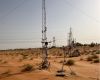
Overview In the heart of the UAE’s Empty Quarter desert—one of the harshest and least hospitable......Leia mais